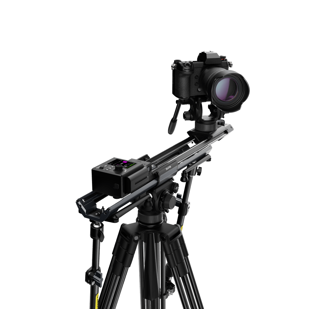
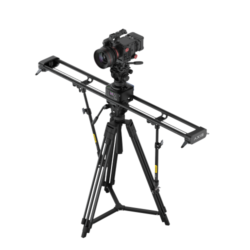
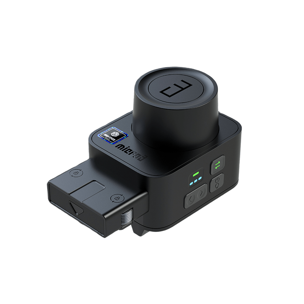
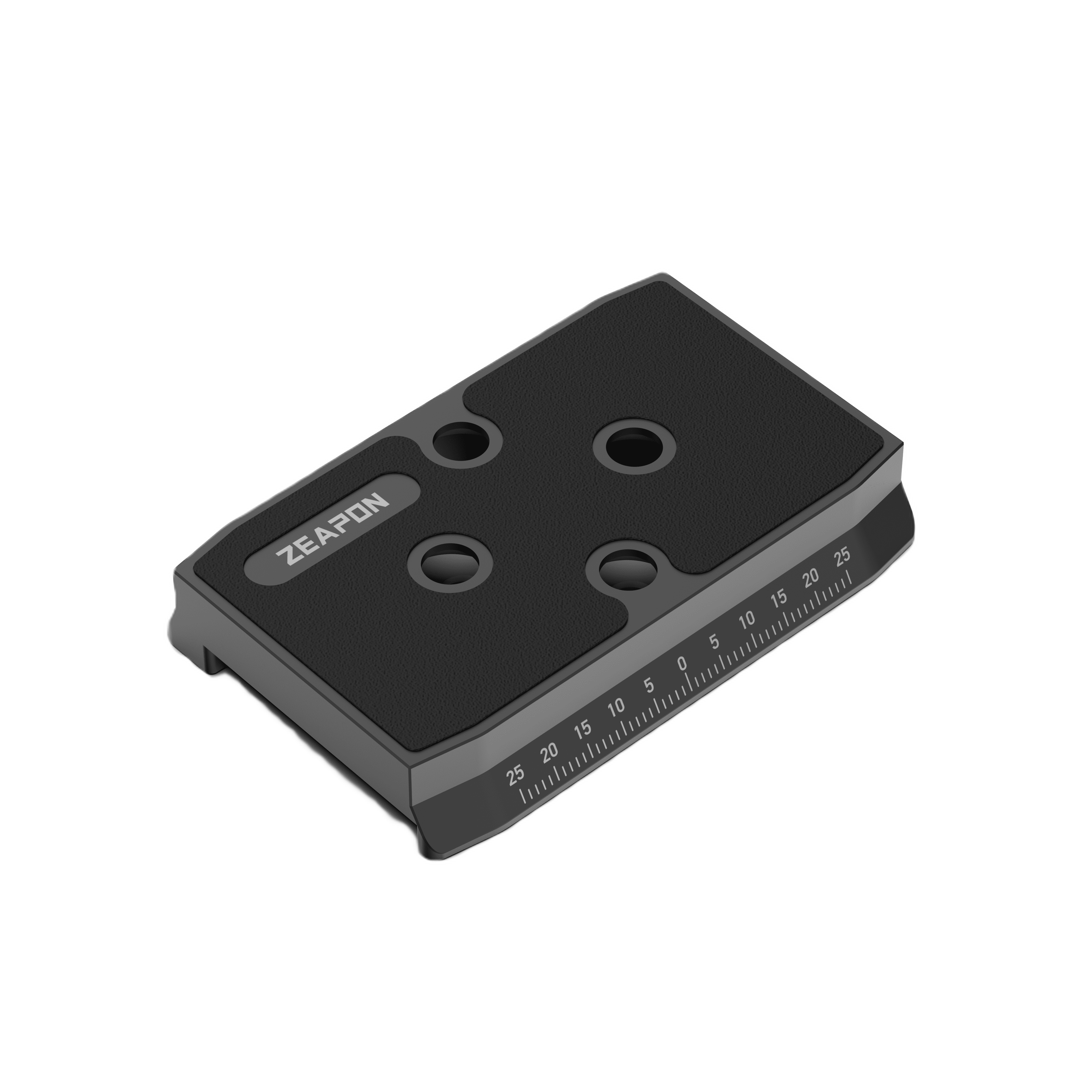
AXIS Multi-axis Motorized Slider
1. This is a new series, which has no inheritance from the 3rd generation of sliders; 2. This series is a single slider, which can provide professional shooting effects in suitable application scenarios; 3. Comes with a 360-degree panoramic head , can avoid cumbersome disassembly and assembly work, and is more efficient; 4. This series has an LCD screen, which is convenient for users to observe the status of the slider in real time; 5. Most of the operations can be performed without the APP, which greatly improves the efficiency of use;
The slider model corresponds to the length of the slider. For example: AXIS 120 total length is 120cm.
(Lens) center point travel refers to the distance from the leftmost end to the rightmost end of the 1/4 screw of the loading platform during the operation of the entire slider. SS-E1 series: 100cm SS-E2 series: 80cm SS-E3 series: 60cm
1. Use the arrow keys on the left side of the screen, or use the manual mode to move the PONS Pan to a suitable position, use the buttons on the vertical PONS Pan to adjust the pitch angle (if necessary), and press the A button (there will be a prompt on the screen) ; 2. Use the arrow keys on the left side of the screen, or use the manual mode to move the PONS Pan to a suitable position, use the buttons on the vertical PONS Pan to adjust the pitch angle (if necessary), press the B button (there will be a prompt on the screen) ); 3. Press the “Play/Stop” button to start running/stopping; 4. If you need to run in a loop, press the “Cycle” button (there will be a prompt on the screen) before starting to realize the loop running;
Long press the hand button to enter the manual dotting mode. After confirming points A and B, it will automatically jump out of the manual dotting operation. The rest of the operations are the same as the process of pressing buttons
The slider must be operated in the order of determining point A first, and then determining point B. Point B cannot be determined first, and then point A;
Because the slider adopts a gear set to increase the transmission ratio and improve the carrying capacity, it needs to overcome the resistance of a part of the internal structure when pushing it by hand, so you will feel resistance
In addition to the time-lapse photography function, the running speed of the slider (including the rotation speed of the pan/tilt) can be adjusted through the dial on the right side of the operation panel.
1. At present, it only supports real-time speed control of sliders and pan/tilts. After adding devices to form a dual-axis system, the real-time speed control function cannot be used; 2. When the time-lapse photography function is running, the real-time speed control function cannot be used, and it needs to be exited and restarted. Setting parameters;
First operate the middle platform to leave the range of the mounting plate, and use the switch at the bottom of the PONS Pan to switch with one key.
Due to structural limitations, the working angle of the slider is different, and the weight limit of the equipment that can be carried is also different. All series of products support: 12kg in horizontal state; 3.5kg in vertical state;
1. The device supports SONY standard NP series F550/F750/F950 series batteries; 2. Supports charging plugs with PD protocol or 5V3A output and higher power; 3. Supports power banks with PD protocol or 5V3A output and higher power;
Simultaneous use is supported. The slider platform provides abundant installation holes to meet various installation requirements.
Under no-load conditions, the highest speed: Running time 550 batteries ≈ 80 minutes 750 batteries ≈ 152 minutes 970 batteries ≈ 251 minutes Running distance 550 batteries ≈ 192 meters 750 batteries ≈ 364.8 meters 970 batteries ≈ 602.4 meters
After setting the path, before starting, you can choose to press the A and B point buttons to run the slider to the starting point, and then start running the path.
Micro3 Series slider
The total travel distance refers to the total length of the space occupied by the double slide rail during operation (excluding the electronic control module).
M1000\E1000 : 1070mm
M700\E700: 770mm
M500\E500 : 590mm
The travel of the center point refers to the distance from the leftmost end to the rightmost end of the 1/4 screw of the loading platform during the operation of the entire slide rail.
M1000\E1000 : 900mm
M700\E700: 600mm
M500\E500 : 420mm
Please refer to the official tutorial: https://youtu.be/y9d0UK8Otpc
Please use one hand to hold the body of the slide rail, and the other hand to push the upper slider where the camera is located.
The damping of the upper slider is only 1/2 of the edge part, which is easier to push.
The damping of the Micro 3 manual version adopts a 5-level adjustment design, and the damping value changes continuously.
When the damping adjustment knob is at the “1” position, the slide rail runs without damping, and there may be a slight sense of frustration; as the number increases, the damping value will also increase, and the sense of frustration will disappear quickly after damping is involved.
Can’t. In order to maintain the uniform motion of the slide rail to the maximum extent, even if the damping value is adjusted to the lowest gear, it still has basic damping.
First, align the positioning steel column and tooth plate of the electric control module with the corresponding installation position of the slide rail, hold the suspended position of the electric control module with your hands, and then move the toggles on both sides according to the direction indicated by the icon on the electric control The knob is locked and the installation is complete. Removal can be done in reverse.
Due to structural limitations, the working angle of the slide rail is different, and the weight limit of the equipment that can be carried is also different.
M1000\E1000: 12kg in horizontal state; 4kg in vertical state;
M700\E700: 12kg in horizontal state; 4.5kg in vertical state;
M500\E500: 12kg in horizontal state; 4.5kg in vertical state.
1. The electronic control module supports SONY standard NP series F550/F750/F950 series batteries;
2. Support charging plugs with PD protocol or 5V2A output and higher power;
3. Support power banks with PD protocol or 5V2A output and higher power;
Simultaneous use is supported. The slide rail platform provides abundant installation holes to meet various installation requirements.
Simultaneous use is supported. The slide rail platform provides abundant installation holes to meet various installation requirements.
Micro2 Plus slider
1.Confirm whether the battery is charged.
2. Unplug the battery, reinstall it, and try again
3. Confirm whether the Micro 2 Motorized module vibrates after powering on. If there is, it is estimated that the Hall sensor is broken; if not, it should be that the driver board is broken.
The normal operating temperature of the Micro 2 Motorized module is -20℃~50℃. Exceeding this range will affect the slider. The overall temperature will drop, the bearing will be frozen, and the slider will not move because the damping oil has a temperature limit.
No, the current speed is already at the upper limit. No matter how fast the motor is, there will be problems. If it is too fast, the motor will roar and be weak.
Please find the attached spare belt and refer to the belt replacement video on the website to replace it.
The magnet is divided into two positions: the magnet on the top of the belt buckle is a magnetic attraction function added to facilitate the quick removal of the belt. If the belt is dropped, it can be assembled and used normally, but it is recommended to replace it with a fully functional belt assembly; the other is the belt buckle tail The magnet at the end is to ensure that the Micro 2 Motorized module can work normally. If it is dropped, the belt assembly must be replaced before it can be used.
The Motorized control version of the slider comes with two spare belts with different lengths. The long one corresponds to the belt assembly at one end of the Micro 2 Motorized module, and the short one corresponds to the belt assembly at the other end.
1. The main rail is damaged and has pits. Check for scratches on the sliders that the wheels pass by
2. The small wheels inside the railway are broken. Need to replace the small wheels (there is an operation video)
1. The belt is loose, and the knurled screw connected to the belt needs to be tightened
2. If it is confirmed that the belt is damaged, the belt of the corresponding product model needs to be replaced (spare parts are available)
Yes, you can purchase the corresponding Micro 2 Motorized module separately.
The sensor is broken, it is recommended to return to the factory for inspection and repair. But for sure the issue, better consult the technical support team.
Considering that the bottom is scraped, the small wheels inside may be crushed. Replacement of the small wheels and the main rail is currently a more appropriate treatment method.
PONS PT Pan and Tilt Head
Make sure the PONS heads have been upgraded, go to the Zeapon lab mobile app, and connect both PONS head settings- firmware upgrade. After upgrading, make sure you place to PONS heads vertically on a horizontal surface, if you are confused about what’s that means, just attach heads on your slider, which helps internal sensors work perfectly, and now you are good to go.
Absolutely, but you have to use the Zeapon lab mobile App to accomplish that, cannot use buttons to do that.
We’re working on that, and shall resolve the pause in the next-generation app, if everything goes well it will be released before 2023.June
With one PONS head, you can purchase another tilt arm kit and another PONS head to make them work together.
Yes, for all motorized Zeapon slider, PONS heads work with them perfectly, but make sure you upgrade the firmware for your slider.
You need to make sure the camera gravity point is well placed on the arm kit, check the video to know more: https://youtu.be/bzFYV8rVgtI
Yes, but work for PONS head only, which means horizontally rotate ok and with tilt head it will have 4 kg payload.
You cannot, there is no internal battery inside of the PONS head but you can actually use a USB-c cable with a normal phone charger to make it on power.
For now, you cannot have photography like that with PONS, we will consider optimizing the matrix mode in the App and making it more functional in VR filed.
Zeapon LAB APP
1.There is a problem with the shutter cable, check whether it is a special shutter cable for the applicable model
2. Port of the camera or motor has an issue(consult sales for support).
3. Check the cable is not reversed plugged in.
1. Confirm whether it is MF manual focus
2. Confirm whether it is a single shooting mode
3. Change the camera and try to see if there is a problem with the camera settings
4. If it is a Canon camera, you can download a new firmware package on the official website to upgrade and then open the APP to try to shoot
Do not click the waypoint to move, click the start button underneath.
Make sure Bluetooth activate and works properly, and make sure there are no other devices connected to them when you are trying to connect.
Yes, adjust the speed to 1% you bearly see slider moving.
Please make sure you are not operating the virtual joystick, they just move with the range of your dragging, Adjusting the speed to 100% will influence the speed on the slider after you click the start button.
We are working on it, but you can still use after effect to speed up some of the footage to get a similar result.
There you go:


